
OK, as promised—twice—let’s talk input stage. This is the (surprise) requirement I have been alluding to:

When hooked up super-directly (the way I like it) the input tube (left) has the full plate voltage of the driver tube (right) over it, plus the voltage drop of the choke (a couple of volts), minus the grid bias of the driver tube. The last one being negative, it ads up. Taking the numbers from the first post, that is 300V over the 2A3 + 8.75V over the choke - (-65V) on the 2A3 grid = 373V (and a bit) of plate voltage for the input tube.
And that is a too much for a lot of tubes (among them the 2A3). You can do two things about that. One is to use an input tube that can take it. The other is to burn a good chunk of those volts in another way. This is what jc does:

The resistor on the kathode of the input tube biases it, the one under it is there to drop quite some volts. In a recent blog post by jc we can see how much:

160V gets dropped over a 10k resistor. There is a price to pay for that, however. The western electric 437A is one hell of a tube. At jc’s operating point, µ ~ 40 and rp ~ 1k. But, the 10k is added to that. The kathode resistor adds an additional (40 + 1) × 150 = 6k15. Adding it all up, the input stage is driving the next stage with an impedance of 17k. Going purely by numbers, all that is left over of the magnificent WE437A is sort of an ECC81/12AT7. Actually you'll have to work hard to get an rp as high as 17k out of an ECC81.
Another example is the 76 that Thomas proposed as an input tube. With 250V max rating, it cannot take the 373V on its own. Let’s try some strategies to pad it with resistors:
- max plate volts
- With 250V on the plate, how much plate current can the 76 take? A search shows that max plate dissipation of the 76 is 1.4W. Thus max plate current at 250V = 5.6mA. Bias is -13V at that point and rp 9k5. The dropper resistor is then (373 - 250 - 13)V / 5.6mA = 19k6. The kathode resistor adds an additional (13.8 + 1) × 13V/5.6mA = 34k4. Grant total: 63k5.
- max plate current
- This occurs at the highest grid bias at max plate dissipation. How high can we go? We know that for headroom reasons the tube has to output 65V peak. This means it needs to be biased at least at 65 / 13.8 = -4.7V. From the curves this is at 155V, 9mA. The dropper resistor is then (373 - 155 - 4.7)V / 9mA = 23k7. The kathode resistor adds an additional (13.8 + 1) × 4.7V/9mA = 7k7. Grant total: 40k9.
- muddle in the middle
- The middle along the max plate dissipation hyperbole is √(250 × 155) = 197V. Plate current is 7.1mA at this point, bias is -9V. The dropper resistor is then (373 - 197 - 9)V / 7.1mA = 23k5. The kathode resistor adds an additional (13.8 + 1) × 9V/7.1mA = 18k8. Grant total: 51k8. muddle indeed.
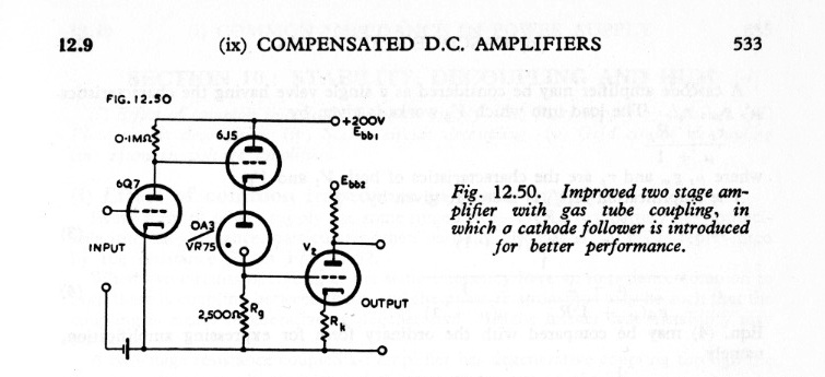
As I have said before, I consider wasting AC—music—power the biggest crime in audio. Hence I prefer to use tubes for the input stage that I can connect directly, that can take the full voltage: the 10Y takes 425V and the 205D 400. And to use fixed bias. Before I move on for ever from this topic, here is another community pointer. I recently recalled reading in RDH4 about direct coupling with VR tubes. Ah, there it is:
Cool, no? So we could use something like this here, which would add an impedance of 60–100 Ohms instead of 10–23k:

Don’t ask me what the start-up and shutdown behaviour of this circuit is. Those who want to try this will have to figure that out themselves.
The last thing I want to discuss today is loading the input stage and biasing the driver stage. These are connected. To get full µ out of the input stage, there are AFAIK 2 possibilities:

On the left we see jc’s plan: a current sink loads the input tube for full µ. It is adjustable so that I/V converted by the plate resistance of the input tube, the bias voltage of the driver stage can be dialled in.
On the right we see the alternative: choke loading of the input tube, with an adjustable bias supply controlling directly the bias of driver stage. Note that this circuit can be referenced (attached to a power supply) either to the left or the right of the adjustable bias supply.
At the moment of writing I find the current sink option more elegant. But the final decision about this can only be taken when the complete picture is there, with the complexity of the current sink and bias supply are known (the latter needs to be designed anyway for the output stage), including power supply integration.
For the current sink, I’d like to make use of the fact that for tubes, large DC voltages, large voltage swings and heat dissipation comes natural. Cascoding a tube over a solid-state current sink that can bring some long-term stability looks appealing:

Voices in my head are discussing the merits of triode or pentode for the tube. For a current sink I am checking out something as simple as a ring-of-two, or something derived from the nifty voltage reference in the teddyReg. Then again, if you start with building a very good voltage source…
hey peter, great to see you working so hard on this! a couple of points, although i can't do a proper considered response here: just the quickie version (going home to sweden from munich tomorrow...) it is incorrect to lump the 10k dropping resistor with rP. it is not. it is in series with the load, and not part of rP. this does create a voltage divider, but 10k down to half a megohm (probably more) is a very small attenuation. i believe i measured something around 0.5 dB. even though this is technically a grounded cathode circuit, the signal is still taken from the cathode. it behaves a little differently than the usual situation where the signal is taken from the plate. however, and here you have a point, it does have an impact on clipping behavior and obviously output impedance. but it does NOT turn the 437 into a 12AT7! hahahahahhaahahahahah! level shifting is always a feature of DC amps and this one is no exception. your level shifting circuit with the VR tube is the classical analog computer arrangement, works very well, except for the broadband noise of the VR tube. which is very difficult to remove... however, you are almost at an improved version of it with the design of the amp as originally presented. all you need to add is a cathode follower after the level shifting resistor. i considered doing it but the DA100 needed to be protected and limited. the 10k resistor does many jobs! however, with an available tube such as the GM70, a different situation presents itself. a buffer at that point is justified, with the caveat that the driver tube will be freer to be it's lovely bad self. an A1 situation at the output does not require buffering the driver stage. there are other ways to achieve the DC drop required without using a resistor: a diode with an rP of 10k would drop in. this can be "constructed" from another tube (triode or pentode) wired as a diode and having it's heater voltage adjusted to reach the rP required. if you want to be punk (directly heated low mu tubes are officially status quo in our world now... the most unpopular thing you can do is hybrid or easily available TV tubes), consider a string of leds, in rainbow colors, or (god forbid) 1N4148's in a long ridiculous string... now you have low impedance and the necessary drop. etc. i think you can afford to be bold here... who cares other than you?! well, i do! i care for my friends. good luck! i'll check in soon... gotta go to the airport.
ReplyDeletejc